Thermal shock testing evaluates how a product responds to rapid transitions between extreme hot and cold conditions. These transitions can occur in seconds, not minutes. The purpose of the test is to replicate stresses caused when materials expand or contract at different rates, creating internal strain that leads to failure.
Unlike thermal cycling, which gradually ramps temperature over time, thermal shock intentionally bypasses controlled ramp rates. Components are moved quickly from one temperature zone to another to create maximum differential stress. This technique often reveals failure modes that do not appear during steady state or slow transition testing.
Thermal shock testing is widely used in aerospace, defense, automotive, medical, and rugged industrial applications where electronics frequently experience sudden temperature changes during storage, transport, start up, or environmental exposure.
How Thermal Shock Differs from Thermal Cycling
Thermal shock can be confused with thermal cycling, but they are not the same.
Thermal cycling
• Temperature changes occur at a controlled rate
• The purpose is fatigue assessment over many cycles
• Stress is lower because materials adjust gradually
Thermal shock
• No controlled ramp rate
• Samples transition rapidly from one chamber to another
• High strain is introduced because materials have no time to equalize
• Used to reveal defects in materials, solder joints, adhesives, and interfaces
This distinction is emphasized in both MIL-STD-202 Method 107 and IEC 60068-2-14.

Real World Scenarios That Create Thermal Shock
Thermal shock events can occur naturally in many environments:
- Moving equipment from a cold aircraft cargo hold to a warm flight deck
- Starting a ground vehicle in subzero temperatures
- Electronics stored in unheated enclosures and powered on rapidly
- Outdoor equipment exposed to direct sunlight after nighttime cooling
- Transitioning between altitude levels where ambient temperature rapidly changes
Understanding these transitions helps Grayhill tailor test conditions to match real world use.
Key Test Parameters Defined by Standards
Thermal shock testing is governed by strict parameters that affect stress severity:
Transfer time
How long it takes to move the product between temperature zones. Short transfer times increase stress.
Dwell or soak time
How long the product remains at each extreme. Enough time must be given for the product to reach thermal stabilization.
Recovery time
How long it takes for the chamber and product to return to the new set point after transfer.
Temperature delta
The difference between the hot and cold extremes. A larger delta produces more strain.
Number of cycles
Typical programs include 10 to 100 cycles depending on the application.
Both MIL-STD-202 Method 107 and IEC 60068-2-14 define acceptable ranges and procedures for each of these parameters.
![]()
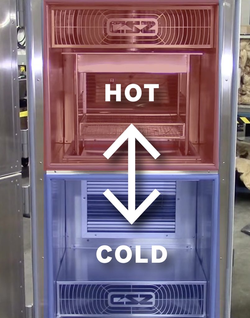
How Thermal Shock Testing Is Performed at Grayhill
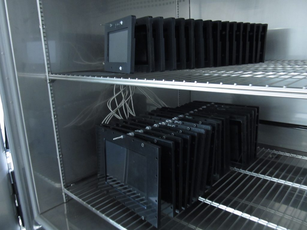
Grayhill uses two-zone and three-zone thermal shock chambers. These chambers maintain precise hot and cold temperatures and allow rapid movement of products between zones.
Engineers monitor:
- Mechanical integrity
- Solder joint performance
- Connector retention
- Adhesive and coating behavior
- Visual evidence of cracking, delamination, or warping
- Electrical continuity and functional response
Special attention is given to temperature stabilization. Some standards require embedding thermocouples within representative samples to confirm internal thermal balance before transitioning to the next zone.
Common Failure Modes Caused by Thermal Shock
Thermal shock can reveal:
Cracking and fracture
Plastics, ceramics, and glass may break when internal stresses exceed material strength.
Solder fatigue or separation
Rapid expansion differences between PCB laminates and solder joints can create fractures.
Delamination
Multilayer assemblies or coatings can separate due to thermal strain.
Mechanical binding
Interfaces with mismatched coefficients of thermal expansion may bind or stick.
Electrical drift or intermittent behavior
Stress can cause changes in contact resistance, insulation resistance, or signal continuity.
Explaining the specific mechanisms helps engineers evaluate whether observed failures indicate design, material, or process weaknesses.
How Thermal Shock Data Supports Engineering Decisions
Thermal shock results help engineers:
- Select compatible materials
- Validate adhesives or coatings
- Confirm solder joint reliability
- Determine acceptable process margins
- Redesign interfaces or housings where strain concentrations occur
For customers, this means greater confidence that components can withstand real world rapid temperature transitions without mechanical or electrical degradation.
Summary
Thermal shock testing is a powerful method for identifying failure modes that steady temperature tests cannot detect. It provides insight into material behavior, interface stresses, and long-term durability. By following MIL and IEC standards and tailoring conditions to customer applications, Grayhill produces products that remain reliable even when exposed to rapid environmental transitions.